


by Tom Kirkland, owner, tributek.us
Plastics welding has come a long way since people were doing hot plate welding on an electric griddle they bought “down at the Sears and Roebuck.” Equipment has improved while materials have changed and become both more consistent and sometimes more challenging to weld. Primary processes have become more consistent. Most of all, understanding of what is actually happening in a weld has become clearer. To obtain optimal joint strength, molecular orientation parallel to the joint line needs to be as low as possible while leaving the least residual stress in the joint.
Thermoplastics
Thermoplastics are made up of long chain molecules composed of smaller molecules joined together like a freight train. Molten molecules can be thought of like spaghetti coming warm and slippery out of the pot, taking the shape of whatever vessel they are placed in. As they cool, they lose their mobility and shrink.

Amorphous materials have no organized molecular structure. They don’t really freeze either. Their flow just slows down to the point where the material seems solid. Higher temperature results in more freedom of molecular motion and lower temperatures result in less.
Semi-crystalline molecules would love to form complete crystals, but they are so long and entangled that they can’t. So they do the next best thing: Different segments of the molecules form crystalline structures surrounded by a chaotic amorphous matrix. Depending on molecular weight (molecule length) some molecules may join several crystalline structures along their length, while the segments that don’t join crystals help make up the amorphous matrix. Crystals form only in a narrow range of temperature, so slow cooling results in larger crystals and faster cooling in smaller ones. Also, heat is required to break up crystals (heat of crystallinity) and heat is given up in their formation, so specific heat (the amount of heat required to get a given change in temperature) spikes upward when transitioning this temperature range. If temperature allowing a true molten state in the weld joint is not attained, there will be, for all intents and purposes, zero joint strength.
Glass transition temperature is that temperature at which the material exhibits almost no ductility (high brittleness). Vinyl automobile seats a generation past frequently exhibited this in the middle of a Minnesota winter. Older cars with vinyl seats and near-arctic use history were often missing large patches of vinyl that had simply cracked and flaked off on mornings of bitter cold, quiet darkness and agonizingly slow starter motor turns. Thankfully, most thermoplastics products are specified for use well above glass transition temperature.
Primary processes: Extrusion and injection
Generally speaking, at this moment most production plastic welding is done on parts made by injection molding or extruding. Imagine extruding a sheet of fresh-cooked spaghetti about 25 by 400 mm through a freezing cold die and into a freezer. The end result would be a board-like structure held together by ice (which is a decent analogy for affinity bonds among like molecules) and some degree of entanglement of the noodles, with a large portion of the spaghetti noodles oriented in the direction of extrusion. Those that would not or could not orient in the direction of extrusion would contribute more to the transverse tensile strength of the board while those that became oriented to the extrusion direction would contribute more to the longitudinal tensile strength of the board. All analogies are imperfect, but this is a useful mental model of a part extruded with an amorphous material.
The only difference with semi-crystalline materials is that one would note that most of the crystals were elongated in the direction of extrusion, and the orientation of molecules was similarly oriented mostly in the direction of extrusion. Remember, the slower the material cools, the larger and more plentiful the crystal structures.
Almost all flow of thermoplastics in injection molding is parallel to mold steel, and the joint surfaces worked with are similarly parallel to mold steel, so the same mental model applies.
Production plastic welding processes
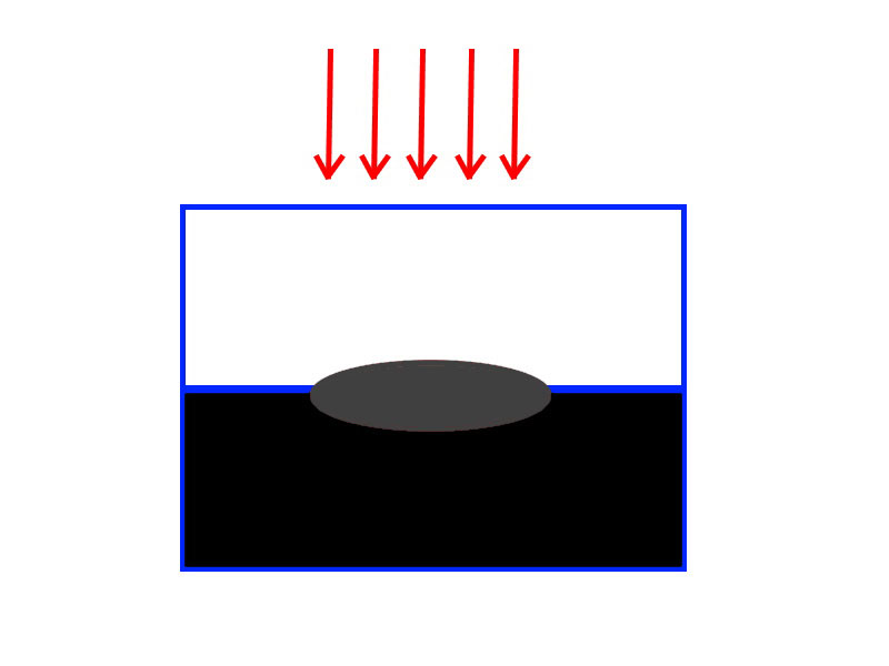
Production plastic welding processes are classified by the method by which heat is applied to melt the joint interface. Basic hot plate uses hot plates, laser uses coherent light, infrared uses non-coherent light, ultrasonic uses high frequency pounding vibration focused in a small area, vibration and spin welding use sliding surface friction. Some processes combine infrared or laser with a thermal or frictional process to gain certain advantages, such as greatly reduced particulate from preheating joint areas with infrared before vibration welding. Collapse in the joint area occurs in all processes except through-transmission light-based processes, such as focused infrared and mask and traveling beam laser welding using fully captured flat joint surfaces.
Application of heat to the joint area
Applying heat is necessary to allow the molecules freedom to flow and form new structures in the joint area.
First, any molten plastic material exposed to room temperature air is going to form a skin of oxidized molecules that are not going to contribute to joint strength as fully as non-oxidized material. This is most readily seen in contact hotplate welding where, in addition to being exposed to air during the time it takes to get the hot plate out of the way and press the two parts together (changeover time), the plate itself retains some residue of damaged material. So, the hot plate process depends on the generation of flash to break up and disperse this film of oxidized material in an effort to approach base material strength. Spin and ultrasonic welding deal with this issue both by generating flash and by closing the joint quickly. Vibration welding allows very little air contact with molten joint material, and the through-transmission laser or infrared processes do not allow any.
Second, generation of particulate is a normal byproduct of both spin and vibration welding, unless infrared assisted, because the initiation of linear surface friction results in a ramp up of heat that takes the thermoplastic through a highly viscous phase that is perfect for rolling up tiny balls of material that quickly find their way out of the joint. Generation of particulate in ultrasonic welding is dependent on both joint design and material. Particulate may be composed of mechanically damaged material and, to some small degree, will be present as tiny points of weakness in the finished weld.
Molecular orientation
The perfect weld joint would have zero molecular orientation. Only the through-transmission processes can hope to achieve this, with hot plate possibly coming close. Remember, the goal is to join two surfaces that start off with a high degree of molecular orientation parallel to the joint. An analogy is trying to glue together two wooden boards on the side-grain, wood’s weakest direction.
To overcome the tendency to high molecular orientation, the goal is a heat-affected zone as large as possible. The deeper heat goes into the part, the slower the joint will cool and the longer the molecules will have to wander into an orientation that gives good joint strength.
Consider a weld made on a hydraulic or pneumatic hot plate welder. The temperature of the plate must be near but not above the degradation temperature of the plastic. The higher the temperature, the faster the heat transfer. The heat affected zone grows into the plastic in a declining exponential fashion, as the material at the interface approaches degradation temperature and becomes susceptible to oxidation. During this time each piece is typically collapsed about 0.5 mm over the first second or two and then held motionless against stops in the tooling until the heat time is over.
Changeover time generally happens as fast as the construction of the machine allows and the parts are pushed together, now collapsing about one millimeter over the first second or two until the tooling again hits stops and the assembly is held until the cool time is over.
The process produces a large amount of flash that carries away the damaged material. The strength of the joint will depend on how well the transverse motion of flash carried this damaged material away, the depth of the heat-affected zone (itself dependent on the temperature of the plate and the heat time) and the level of residual stress.
Several years ago at an SPE ANTEC meeting, a paper was presented by a graduate student from The Royal Military College of Canada in which optimal settings for hot plate welding were explored. For most of the materials studied, the best strength resulted from heat time of 13 seconds and cool time of 13 seconds. There was some very gradual fall-off of strength beyond 13 seconds of heat time, probably as a result of material degradation, and no difference in strength beyond 13 seconds of cool time because, well, done cooling is done cooling.
These were for representative samples of common hot plate welded parts that usually would see heat and cool times set closer to four seconds, maybe eight, but never 13. This is because manufacturing is a series of tradeoffs and sometimes consistently attaining good enough with a fast cycle time is more important than consistently attaining optimal joint strength. But the lesson here is that most hot plate welds are probably weaker than they could be because the heat affected zone was not as large as possible nor was the part cooled long enough to return it to a state from which it could continue to shrink with minimal residual stress. To obtain optimal joint strength, molecular orientation parallel to the joint line needs to be as low as possible while leaving the least residual stress in the joint.
Residual stress is the result of the plastic shrinking as it cools. Plastic weld joints are generally left with some residual stress, as all extruded and injection molded parts are. Faster cooling generally results in both higher residual stress and higher molecular orientation parallel to the joint plane.
So, if in a through-transmission weld, it was possible to heat with a large heat affected zone and cool slowly enough to leave minimal residual stress, it should be possible to attain very nearly as-molded or as-extruded strength. Such a weld will take a long time and probably still have a stress riser at the edges of the welds. But again, all of engineering is a series of tradeoffs. For example, it may be possible to build an airplane fuselage that could perfectly protect its occupants in most crash scenarios but in all likelihood, it would be too heavy to fly.
Collapse vs. through-transmission processes
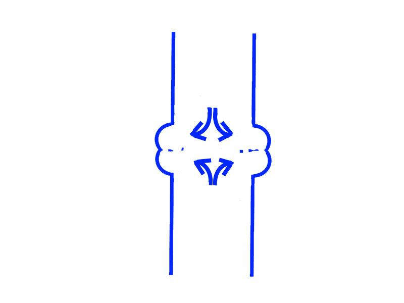
The short answer to the question of why non-collapse through-transmission processes get closer to as-molded strength than collapse processes is that collapse processes produce flow in the molten plastic as a result of the collapse action that is generally parallel to the joint plane and therefore promotes molecular orientation that is parallel to the joint plane. Dr. David Grewell, currently of North Dakota State University, is believed to have coined the term “reptilian flow” to describe this transverse movement of material out of an ultrasonic weld and away from the energy director, which is the heat source.

As previously mentioned, hot plate welding, a collapse process, is a close second to the through-transmission processes at getting near as-molded or as-extruded strength. This is because most hot plate welds are larger than the nominal wall. As the flash slides out of the weld joint it widens the weld, increasing the strength proportionally. The reason flash does not make a vibration, spin or ultrasonic weld stronger is that hot plate flash is formed slowly and is a smoother ductile-state form of flash than the quickly formed knife-like brittle flash typical of the faster processes.
It is possible, especially in spin or ultrasonic welding, to design “flash traps” that contain flash and may allow the “flashed” material to contribute to a good weld. Good examples are the full tongue-in-groove joint, whether with energy director or shear joint.
Thoughts on fillers and reinforcement
Fillers like talc or other minerals displace weldable polymer and the surfaces of the part tend to be filler-rich, so there may not be a strategy that can make the part strong enough without some thoughtful design work in the joint area.
Reinforcements such as glass or carbon fibers will lie parallel to the joint plane and are very unlikely to cross the joint plane, so the joint will never be stronger than some fraction of the basic resin material strength. Also, the surface tends to be reinforcement-rich as well. Imagine a reinforced concrete structure with no steel reinforcing bars crossing a critical structural point. Increasing the joint area may be the only path to more joint strength.
Fillers simply displace weldable polymer and again, the surfaces to be welded can tend to be filler-rich. Hot plate welding with filled or reinforced materials is going to mean a lot of filler or reinforcement residue left on the plate, so it is possible an automatic plate scrubber or a moving roll of “butcher paper” may be needed to keep the plate contact surfaces fresh and consistent.
Practical application of these concepts

All welding applications in the real world are going to have some constraints. For example, if a hot plate weld must produce three assemblies per minute, 13-second heat and cool times will not be used, and the optimal settings will still have to accept less-than-optimal joint strength. This does not mean the part or process is bad, because the definition of a good part or process is that it consistently does what it needs to do.
Assuming the scenario is that any reasonable cycle time is fine so long as the joint is strong, depending on the material slowing the process down in both the heating and cooling phases will probably produce more strength. Ultrasonic welders that can adjust both amplitude (roughly analogous to heating rate) and collapse velocity during weld and during hold will generally produce higher strength when intelligently programmed than simple pneumatic machines. This is because greater control over the process allows for controlled slower velocity and less amplitude, especially late in the heating time, which stretches out the heating time and allows for a larger heat-affected zone (high amplitude can produce damage as well as heat) reducing adverse molecular orientation as a result of transverse flow of material and residual stress.
Something as simple as a mechanical stop on a pneumatic driven ultrasonic welder that allows ultrasound to continue running for a short time after slide motion has stopped can, with many materials, increase the joint strength without making an assembly that comes up short of a height specification.
Velocity can be reduced on a vibration welder, traverse speed and power reduced on a traveling laser welder, cool/hold time increased, clamp force reduced during cool/hold, etc. If cycle time has to be reduced without giving up too much strength, look to increased intensity of heat generation early in the heating part of the cycle tapering off and a minimal hold/cool time, possibly with reduced force.
Understanding the material – such as knowing that polycarbonate or mineral-loaded materials tend to have higher thermal conductivity than some others and polyamides are low in viscosity when they melt and like a faster joining velocity, or that slowing down the heating rate of the process can help prevent foaming in joints of clear acrylic assemblies – can be vital.
Sometimes less weld done better is better than more weld done poorly. This is very much the case with ultrasonic welding, where continuous joint around the entire perimeter of a part is often less strong than intermittent joint segments. Understanding the conduction of heat to the joint and the means of applying the clamp force required to make the joint also are key.
Some part geometries are just going to be easier to join with particular processes than others. Part geometry has a tremendous bearing on the ability of tool designers and process designers to come up with a robust manufacturing system that will produce consistent results. Further, no joining process should be expected to produce assemblies of higher quality and consistency than the parts delivered to it.
There’s a saying in aviation: “It’s not what you know, it’s what you can think of in time.” When a welding process crumps and there are hot orders to be filled and the weekend is coming up fast, it can be hard to think clearly. In that moment understanding the process and thinking like molten plastic will probably result in making the right adjustments to put the process right again.

Tom Kirkland is the owner of tributek.us, a supplier of converters, boosters, parts and supplies for ultrasonic welding machines. He is a consultant, trainer and author of many papers and articles on plastics assembly. For more information, email info@tributek.com.