


by Tom Kirkland, owner, tributek.us
A few decades ago, ultrasonic welding was thought to be a “black art,” and somebody in the manufacturing organization was designated as “the priest” to minister to the whims of the process and equipment. When something went awry, sacrifices of time and money needed to be made to appease the angry spirits for a period of time before stable production was restored.
As knowledge of the process increased, molding got more consistent and the machinery itself became more robust, many of the old-time head-scratching problems have vanished or diminished. But even today, machine components and tooling need to be replaced for a variety of preventable reasons.
How ultrasound is produced
Electrical power comes from the building wiring at 100 to 250 volts, AC at 50 or 60 Hz, and is converted by an ultrasonic power supply (generator) into the operating frequency and voltage needed to run the ultrasonic converter (transducer), booster and horn (sonotrode) assembly or “stack” in the proper resonant mode.
In olden times, power supplies basically were modified audio amplifier designs driven by an open-loop oscillator. On older manual-tuning machines, an ultrasound “test” was run at operational amplitude and a potentiometer played off against a capacitor to adjust the oscillator frequency and was manipulated to produce the lowest current flow to the idling stack. Early automatic tuning units used error-corrective circuits to hunt for and maintain the frequency sweet spot. Today, state-of-the-art systems use the electrical noise produced by sound waves moving through the ceramics in the converter as a way to track and maintain optimal running frequency for the tooling under changing conditions whenever ultrasound is on. Most of the best industrial ultrasonic systems will protect the power supply against most of the acoustic and electrical loads that could cause damage. This can lead to a false comparison between system vendors when a certain horn will run on machine “A” but not on machine “B.” Possibly machine “B” is sensing something wrong that machine “A” does not. If users are interested in long-running trouble-free production, investigating why machine “B” will not run the tool is a worthy endeavor.
The converter
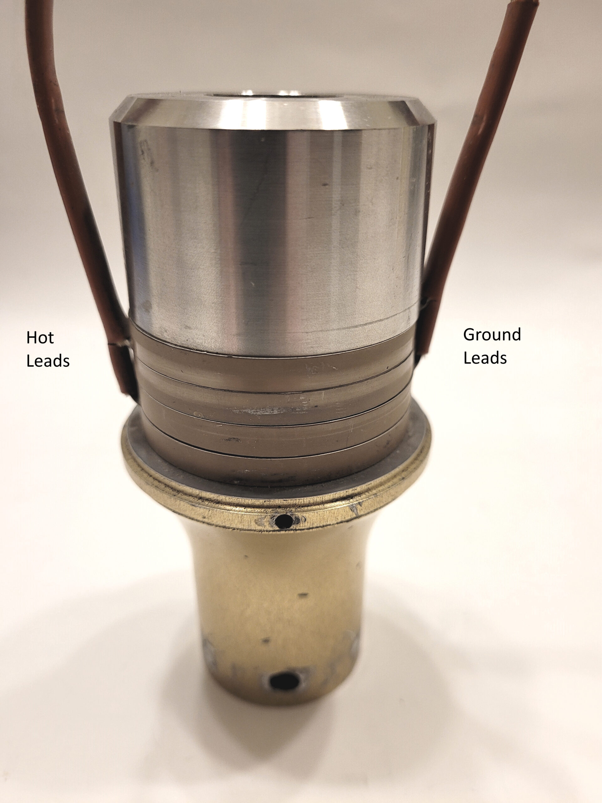
The heart of the converter, the driver assembly (Image 1) consists of three masses clamped together by a center bracing bolt. The rear mass is a cylinder, typically of a steel alloy, which makes it the most dense component. As Bobby Darin said in the song “Mack the Knife,” “it’s just there for the weight, dear.” In the middle of the sandwich is the ceramic mass. The ceramic used in essentially all commercial ultrasonic welders is type 8 lead-zirconate-titanate (PZT). The European Union has been trying to outlaw lead in all products for about two decades now, but no other material yet discovered exhibits piezoelectric properties (conversion of electricity to motion and motion to electricity) as strongly as PZT.
Deadlines have come and gone and still the power transducer industry manages to get last-second limited exemptions to the EU directives. If this ever changes, it will be devastating for the owners of existing ultrasonic machines in the EU and for future machines used there, which will have limited performance compared to machines produced and installed elsewhere in the world. The front mass of the converter typically is aluminum or titanium. Titanium has about half the density of steel, and aluminum has about one third the density of steel – although, in practice, all three have a similar speed of sound. The three masses are clamped together with precisely controlled force by a center bracing bolt.
The ceramic mass is a series of precisely manufactured PZT discs which have been cured in a strong magnetic field, such that the ceramic grain direction is oriented to enhance the piezoelectric effect in the direction of the thin dimension of the discs. This orientation becomes frozen in position as the ceramic cools through about 80° C to 50° C. This “poling” of the crystals allows the discs to grow or shrink in thickness in unison with the changes of flow direction in the alternating current provided by the power supply. Each disc expands when current flows in one direction and shrinks when it flows in the other.
The discs are stacked in pairs such that foil electrodes placed between the discs are set up with the ground electrode of the AC circuit typically against the rear mass (ensuring grounding of the ultrasonic tooling) or an adjacent pair of ceramics if one exists, with the hot leads between the members of a pair. Each pair then represents two parallel electrical circuits. While a few commercial welding converters have only one pair of ceramic discs, most have two pair and many have three. A few high-power converters have had four pairs. The consistency of chemistry, dimensions, surface conditions and sintering of the PZT has to be very high to balance the electrical circuits so all of the discs do a similar amount of work, which leads to production of a reliable converter.
As the ceramic mass grows and shrinks in the axial direction, it actually pushes the two other masses farther apart and then allows them to return closer together than they were at rest in harmony with the AC electrical signal. The stretch on the center bracing bolt increases and decreases with each cycle. It is very important that the electrical signal closely approximates a pure sine wave so the stresses on the components are applied smoothly. Any inefficiencies in electrical contact, the application of power and the physical makeup of the components will show up as heat and, as mentioned prior in the discussion of poling, heat above 50° C will degrade and eventually destroy the piezoelectric effect. This degradation increases rapidly at temperatures above about 70° C, and the ceramic is then said to have “de-poled.”
The overall length and configuration of the masses is designed to reinforce the motion of the components and resonate in standing half-wave fashion, with the center of mass near the middle of the ceramic mass, the heavier (more massive) end moving at a lower amplitude (distance traveled in one cycle typically measured peak-to-peak) and the lighter end traveling not only at higher amplitude, but at some known amount of amplitude that is consistent and predictable from machine to machine.
Older machines still in use today mainly are open-loop amplitude machines, while most machines made in the 21st century are closed loop, using the electrical noise signal from the ceramics to ensure the desired amplitude is what is produced. In machines having controllable amplitude, the amplitude usually can be reduced from maximum down to 50% or as low as 30%, depending on the electronic design. Most 20 kHz ultrasonic plastic welders will operate with a maximum peak-to-peak amplitude at the working face of the converter of 20 to 22 microns. Since the converter is changing only in length and not volume, as the device gets shorter and longer it will get larger and smaller in diameter by some small amount, which is at its highest radial amplitude at the node (point of zero longitudinal motion).
The converter driver assembly (the three masses discussed previously and held together by the bracing bolt) requires exacting adherence to good practices and tight tolerances at every stage in manufacture, uses expensive ceramics with long lead times carefully matched into sets, has an exacting assembly process and, after all of that, requires a month of aging to ensure it is within all operating specifications and likely to be highly durable. If handled poorly, it is easy to destroy and expensive to replace.
The booster
The booster is a tuned half wave component that has a positive, neutral or negative effect (gain) on amplitude transmitted from its input end to its output end. This gain is expressed as a ratio. A booster having twice as much amplitude at its output end as its input end is said to have a gain ratio of 2:1 (or 1:2, depending on who you are talking to). Generally, the :1 or 1: is understood and the booster is just referred to as having gain of 2.0. If a booster has no gain, it is 1.0. If it cuts amplitude 50%, it is 0.5, and so on.

The booster typically is made of aluminum or titanium and less often of steel, and it moves in half wave fashion. That is to say, its two ends (antinodes) move in opposite directions and its middle (node) stands still, though the node does have radial amplitude as discussed above. It creates gain by either having more or less mass on the input end than the output end. By the law of conservation of momentum, the lighter end moves farther with the same amount of energy compared to the heavier end. This explains why the rear mass of the converter is made of steel and the front mass is made of a less dense metal (Image 2).
Titanium boosters are more durable and more expensive than aluminum boosters, but aluminum boosters dissipate heat better. The booster has a structurally tough mounting ring placed at the node with either a compliant (inexpensive) or non-resonant all-metal, low-deflection (expensive) connection to the booster body. This ring is designed to deal with all of the thrust and lateral stresses imparted by the clamp loads applied to the ultrasonic horn. This mounting ring is the main reason 1.0 boosters exist, which otherwise would have no function.
The horn
The horn generally is metal in any shape, allowing the laws of acoustics to be manipulated such that clamp loads and amplitude are applied to a workpiece to produce the desired result. The most common materials are aluminum, titanium and steel. Since this is not an article about ultrasonic tooling or applications, we will dispense with further discussion, except to say the some horns and some applications will stress a converter in such a way as to significantly shorten its life. The more optimal the conditions in those situations can be, the less time and money will be spent replacing broken things. There are applications in which the stack can continue to be abused for a period of years, and others in which the stack only will tolerate abuse for a few minutes. Some shops are blessed or cursed with one or the other; some shops will have both side by side.
Optimizing conditions for reliability and durability
Make sure the tooling is properly tuned. If in doubt, check it out. Not only should stack frequency be checked for changes before and after a run (most 21st century machines will display the running frequency), but each component in a “fussy” stack should be checked, annually or more frequently. Tooling is not to be considered to be in good working order just because the machine will run at idle and through a few cycles. If the stack has a problem, it quite often will show up as heat, noise or both. The least stress on the system is in the middle of the frequency range, not at the edge.
Some applications chew up horns. In such a situation, running a horn until it quits is probably not the best way to avoid damaging other parts of the system. Ask the tooling supplier about putting a wear indicator of some kind in the tooling itself or study the application to establish a cycle count or time limit that a horn is online before it goes offline to be evaluated for repair or replacement.
Avoiding shocks to the stack is one of the easiest ways to ensure long life. First, don’t drop or pound on any stack component. A titanium booster or horn may be fine after a drop, but it is much less likely that an aluminum one or a converter will be. Do not allow a running horn to touch metal unless the application specifically is developed with this in mind. The PZT ceramic is a cousin of glass.
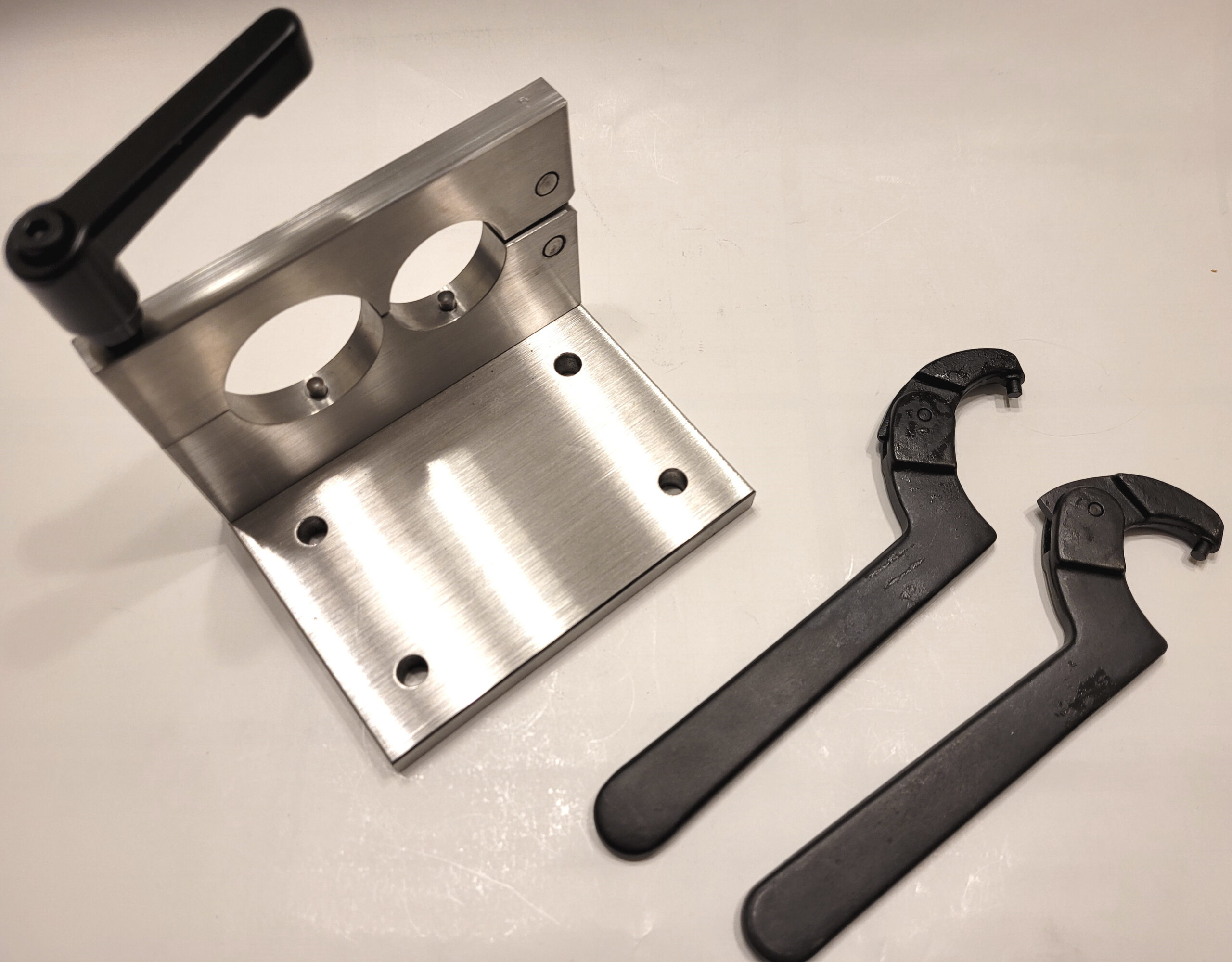
Use appropriate tools for tooling assembly and disassembly. When asked why a converter failed, one often only has to point to pipe wrench marks or severely stretched spanner wrench holes to reduce the incidence of future failures. Proper use of an appropriate type and size of wrench and a tooling vise (Image 3) will tend to sort out many of these issues. Make sure the tooling joints are properly prepared and properly torqued. This topic requires another entire article and happily, one already exists in the April/May 2011 edition of Plastics Decorating.¹
Keep the converter cool. If the converter gets hot, it de-poles and stops being useful, becoming a very expensive paperweight. Some heat sources to eliminate include improperly tuned horns and boosters, poorly maintained stack joints, tooling that heats up because of “cooked” booster O-rings, minor cracks and excessive wear.
It nearly is universal practice in ultrasonic machines with pneumatic power cylinders to use cylinders with Teflon seals and O-rings so that clean and dry compressed air can be used. This is because air exhausted from the cylinder usually is routed to the converter compartment to provide a wash of cooling air during the “down” and “up” strokes. The little bowl filter that comes with the welder is meant to be a last line of defense against wet or oily air, not the entire army. The converters are designed with air cooling holes for this purpose, but if condensate, water/oil mix or dirty oil with microscopic particles of compressor metal in it makes it to the converter driver, converter arcing likely will occur in the future. Converter voltages are, at the very least, in the high hundreds – up to 3,000 volts and beyond. Once a converter has arced from one electrode to another, it becomes a paperweight.
If force-cooling a converter in a high-duty cycle or continuous ultrasound application, turn off the cooling air when the machine stops running. It is best if this shut-off is built into the system somehow so it is automatic. When an ultrasonic stack is over-cooled, it shrinks and can move to or beyond the high-frequency margin of operation. It actually is possible to cool an ultrasonic stack (for example, using vortex coolers) to the point where it is too high in frequency to run at all. At that point, waiting an hour or two with no cooling usually will solve the problem. As above, make sure any cooling air absolutely is clean and dry, especially when using vortex cooling, which tends to exacerbate condensation problems.
Ultrasonic welders last a long time in cleanrooms, often looking and running as though new for two or three decades – or longer. Dirt, dust and liquid water can be a problem for the converter, power supply and other system components and steps should be taken to protect them. Temperature extremes most affect operation by changing the operating frequency of the tooling stack, although in certain very-high-temperature environments, cooling of the converter and power supply needs to be increased.
And finally
All of the manufacturers of ultrasonic welders have operating manuals, technical guidebooks and technical bulletins describing best practices for a variety of situations. These usually are the best source of information about the particular system being used. Great results and great reliability are the fruits of seeking good information about best practices and following them.
References
Tom Kirkland is a manufacturing engineer who has been involved with ultrasonic welding for over three decades. He is considered to be a subject matter expert in plastics welding and has published many articles and technical papers, as well as presented over a thousand seminars and other training sessions on the topic. Kirkland has served on boards and technical committees for several professional associations, is a patentee in the field and past president of the Ultrasonic Industry Association. He is the owner of tributek.us, a supplier of parts and supplies for ultrasonic welders and refurbisher/supplier of quality used ultrasonic systems. For more information, email info@tributek.com or visit www.tributek.us.