


by Miranda Marcus, EWI
Spin welding is a common joining process for plastic parts with circular joints such as insulated cups and bowls, filter housings and valves. In this process, heat is developed from surface friction as one part is revolved about the axis of the joint, resulting in a high linear speed. Finite element analysis (FEA) of the process can aid in determining proper process parameters to achieve sufficient heating for a good weld.
In both spin and vibration welding, there are four stages of the weld: solid friction, unsteady state, steady state and hold. In the first stage, heating is dependent on the relative velocity of the moving part to the fixed part, the normal force being applied and the surface friction of the material. In the third stage, heating is dependent on the velocity, viscosity and melt layer thickness. In this work, an approach to predict the weld temperature based on frictional heating which dominates on the first stage has been investigated and compared to measured results. The approach showed good correlation to measured data for settings with more frictional than viscous heating.
Stage 1 – Solid friction
During the solid friction stage, heat is generated due to surface friction:
Q = FNµrω
where Q is the heat generation rate, FN is the applied normal force, µ is the coefficient of surface friction, r is the mean radius of the assembly and ω is the angular frequency in radians.
Stage 2 – Unsteady state
During the unsteady state stage, heat is generated due to a combination of surface friction and viscous heating until a full melt layer is formed at the joint. This is a very short stage of the process.
Stage 3 – Steady state
During the steady state stage, shearing of the melt layer leads to viscous heating:
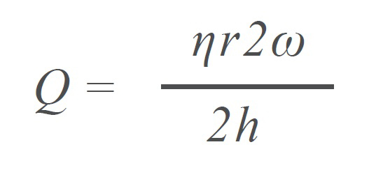
where Q is the heat generation rate, η is the melt viscosity, r is the mean radius, ω is the angular frequency in radians and h is the melt layer thickness on each part – so that 2h is the total melt layer thickness.
Stage 4 – Hold
During the hold stage, there is no heat being generated and the parts are allowed to cool under clamping pressure.
Experimental set-up
A Dukane dual servo spin welder was used to weld the parts. An Instron 4204-145 tensile tester with a 10,000 lb. load cell was used to test the parts.
DuPont Zytel® (HTN 51G15HSL), polyphthalamide with 15% glass fill and a heat stabilizer was the material used.
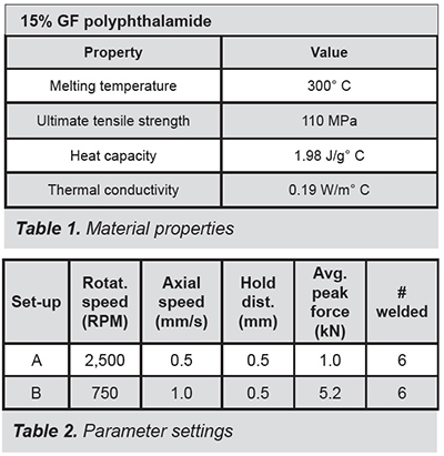 This type of material often is used for production parts that will be exposed to an abrasive environment, such as in an engine. Key material properties are shown in Table 1.
Two parameter sets were used for comparison to the model, as detailed in Table 2. For both set-ups, the rotation of the upper part was initiated before part contact and the weld was terminated at the same position.
Set-up B uses a higher compression force, which will increase the amount of frictional heating per the stage one heat generation equation. Alternatively, Set-up A uses greater rotational speed, which is the sole welding parameter present in the steady state heating equation.
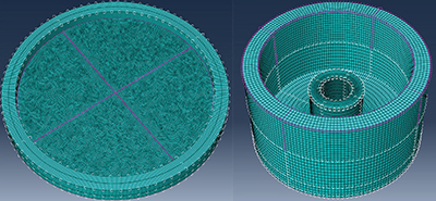
Abaqus CAE 2019 was used to simulate the heat input from the welding process. The mesh used is shown in Figure 1. A heat transfer step was used to apply heat to the top of the base object based on the solid friction heating equation.
Conductance was defined between the base and top objects to transfer the heat from the base to the top object.
Results and discussion
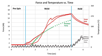
The following welder data are shown in Figures 2 and 3:
- Force feedback data from three representative welds
- Thermocouple temperature data from two welds
- Modeled temperature rise
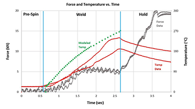
Using the same efficiency coefficient of 1/14 for both parameter sets results is an underestimation of heating for Set-up A, and an overestimation of heating for Set-up B. The most likely cause for this mismatch is that, in this model, heating is predicted solely using the solid friction heating equation. However, the established heating equations predict that, after solid friction heating produces a layer of melt, continued heating is dependent on the rotational speed of the part and not on applied force.
As would be expected based on the weld parameters, parts welded with Set-up B showed more solid particulate, which is characteristic of solid friction heating.
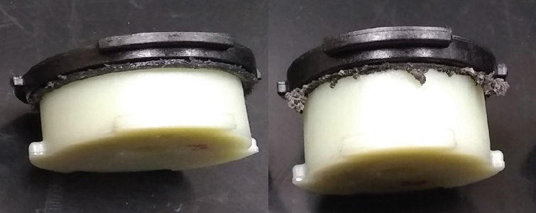
A comparison of the type of flash observed from both set-ups is shown in Figure 4. This visual observation supports the conclusion that Set-up B parts experienced greater solid frictional (stage one) heating and Set-up A parts experienced more steady state (stage three) heating.
Conclusions
This initial evaluation of the ability to conduct temperature prediction of spin welding results based on fundamental heat generation equations and using computer-aided modeling shows that the approach can be effective when the heating mode is primarily solid friction. If significant viscous heating occurs, predicting temperature will be made more difficult by the need to account for the viscosity property, which changes as temperature increases, as well as the need to estimate a melt layer thickness.
Importantly, all initial heat generation for spin and vibration welding processes occurs through a solid friction mechanism. Therefore, modeling solid friction heating gives great insight into the speed of heat generation. For applications where there is asymmetrical geometry, the effect of those geometrical differences on heat generation can be modeled. Thus, decisions about wall thickness, joint design and structural support can be made before cutting steel on an injection molding tool, saving time and money.
Miranda Marcus is EWI’s technical lead for polymer and composite welding. She has extensive knowledge of plastic welding technologies including ultrasonics, laser, spin, hot plate, vibration, thermal staking, radio frequency and infrared.
EWI empowers industry leaders to overcome complex manufacturing challenges and integrate new processes to bring products to market more quickly and efficiently. Since 1984, EWI’s comprehensive engineering services have helped companies identify, develop and implement the best options for their specific applications. To learn more, visit www.ewi.org, email info@ewi.org or call 614.688.5000.